12+ Relay Logic Wiring Diagram Images. The schematic diagrams for relay logic circuits are often called line diagrams. Relay logic control wiring diagram.
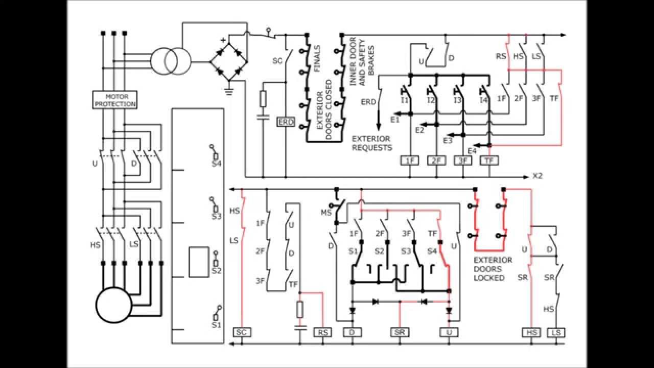
Elevator circuit diagram - YouTube from i.ytimg.com A relay logic circuit is an electrical network consisting of lines, or rungs, in which each line or rung must have continuity to enable the output device. This logic table can be implemented using three relays as shown in the following (left) relay circuit diagram. Relay logic control wiring diagram.
Relay logic is all about wiring up relays for logical switching applications.
The si safety relay logic is set to mm (monitored manual reset). They play a very important role in providing safety critical logic. Electromechanical relay logic this worksheet and all related les are licensed under the creative commons attribution license, version 1.0. Reading guidelines for ac and dc schematics in protection and control relaying (on photo:

0 Response to "Relay Logic Wiring Diagram"
Post a Comment