44+ J K Flip Flop Circuit Diagram Gif. Otherwise, even if the s or. The ic power source vdd ranges from 0 to +7v and the data is available in the datasheet.
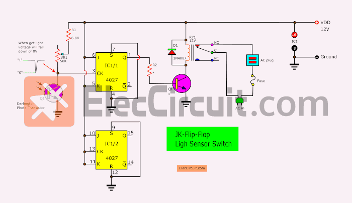
Light sensor switch circuit using JK-Flip-Flop - ElecCircuit from www.eleccircuit.com Construct logic diagram according to the. Otherwise, even if the s or. This is a simple circuit based on transistor 2n 2222a and some resistors, there are 2 led s and when one is complete the circuit according to the circuit diagram,here i have used a common circuit board, there is a simple way to find the polarity of the led ie, by looking for the flat.
Average operating current can be obtained by the following equation.
The s and r inputs of the rs bistable have been replaced by the two inputs called. When j = k = 0, it holds its present state. This is known as a timing diagram for a jk flip flop. This feedback selectively enables one of the two set/reset inputs so that they cannot both carry an active signal to the multivibrator circuit, thus eliminating the invalid condition.

0 Response to "J K Flip Flop Circuit Diagram"
Post a Comment