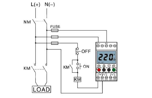
Relay Wiring Diagram 87A
36+ Relay Wiring Diagram 87A Pictures. This circuit diagram of an inactive spdt relay with no power applied to pins 85 and 86 (ground and 12 volt positive). 7 relay locations shows position of the electronic control unit, computer, relays, junctionblock, etc.

In this tutorial we will going to wire the 8 channel relay module driven by our own very owned microcontroller, the below illustration illustrate 8 device on external power source triggered by the relay.
This type of relay allows you to wire two systems (such as a pair of lights) to activate at the. The only suggestion that i would have would be to substitue the + coming from the stock horn if your going. Initially the first circuit is switched off and no current flows through it until. First study the 3 diagrams that you will use as your guide on how you want to built your wiring.
0 Response to "Relay Wiring Diagram 87A"
Post a Comment