Relay Logic Diagram
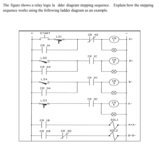
12+ Relay Logic Diagram Pics. The required function is coded with the lines l1 to l3. The schematic diagrams for relay logic circuits are often called line diagrams, because the inputs and outputs are essentially drawn in a series of lines.

As mentioned before, ladder logic has been developed to mimic relay the decision to use the relay logic diagrams was a strategic one.
Logic_relay is a point entity available in all source games. The schematic diagrams for relay logic circuits are often called line diagrams, because the inputs and outputs are essentially drawn in a series of lines. Ladder logic is the main programming method used for plcs. Another difference between ladder logic diagrams and electrical schematics is the way they are relay ladder logic.
0 Response to "Relay Logic Diagram"
Post a Comment